NAVIGATIONMain Page Webmail Calendar Drive VPN Secure Messaging Downloads Fractal TV Antenna Amateur Radio DuckDuckGo Search Send Your Support DESKTOP APPSANDROID APPS |
HOW TO MAKE A FRACTAL ANTENNA FOR HDTV / DTV PLUS MORE ON THE CHEAP
Author: William Ruckman / On: Wednesday 31 December 2008 - 19:26:43
Version 1, Updated 12-31-08. NOTE: I have also posted the information below on instructables.com. After completing this build I always recommend visiting the community there and posting your results, ideas, improvements and so on. It is a very rich resource: Instructables Website This was also showcased in the March 2015 issue of Popular Science Magazine: Popular Science Website Here is a link to the part of the Nova episode that inspired this design (Hunting the hidden dimension): PBS Nova Website The first thing I would like to discuss is a little history, theory, and uses for fractal antennas. Fractal antennas are a recent discovery. First discovered back in 1988 by Nathan Cohen and later published and patented in 1995. A fractal antenna has a few unique attributes as seen in this definition from Wikipedia: "A fractal antenna is an antenna that uses a fractal, self-similar design to maximize the length, or increase the perimeter (on inside sections or the outer structure), of material that can receive or transmit electromagnetic signals within a given total surface area or volume." What exactly does that mean? Well, you need to know what a fractal is. Also from Wikipedia: "A fractal is generally a rough or fragmented geometric shape that can be split into parts, each of which is (at least approximately) a reduced-size copy of the whole,a property called self-similarity." 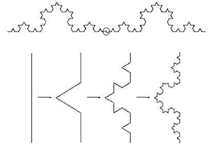 So basically, a fractal is a geometric shape that repeats and appears over and over no matter how far out or how far in you zoom magnification. For visual clarification, here is a picture of the patented antenna: 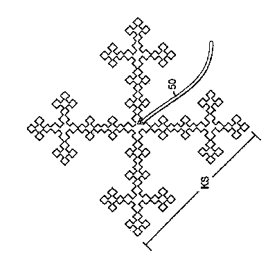 Source: Wikipedia and: Patent number 7088965 Fractal antennas have been found to be approximately 20% more efficient than normal antennas. Which could be useful. Especially if you want to make your own TV antenna to pick up over the air digital or high definition video, increase your cellular range, wifi range, FM or AM radio reception, and so on. Most cell phones already have built in fractal antennas. If you noticed in the past few years that cell phones no longer have antennas on the outside. That is because they have a internal fractal antenna etched on a circuit board which allows them to get better reception and pick up more frequencies such as bluetooth, cellular, and WIFI all from one antenna at the same time!  Wikipedia info: "A fractal antenna's response differs markedly from traditional antenna designs, in that it is capable of operating with good-to-excellent performance at many different frequencies simultaneously. Normally standard antennas have to be "cut" for the frequency for which they are to be used—and thus the standard antennas only work well at that frequency. This makes the fractal antenna an excellent design for wideband and multiband applications." The trick is to design your fractal antenna to resonate at what ever center frequency you wish to receive. Which means it will look different and be sized different depending on what you want to receive. A little math can be used to figure this out. (Or a online calculator) In my example, I am going to make a simple one but you may want to make a more elaborate one. The more elaborate the better. I will use a spool of 18 Gauge solid core wire to make a antenna as an example but you could go as far as to etch your own circuit boards for aesthetic reasons, to make it smaller, or more elaborate with more resolution and resonance. I am going to use the example of making a TV antenna for digital or high definition reception for over the air broadcasts. It is easier to work with these frequencies and they fall around half a foot to a few feet in length for half wavelengths of the signal. I am also going to base it off a common dipole antenna for simplicity and cheapness of parts for VHF. For UHF you may want to add a director or reflector which will also make it more direction dependent. VHF is direction dependent as well but instead of pointing directly at the TV station like UHF you want VHF rabbit ears (dipole antenna) to be perpendicular to the TV station. But there is a little more design to that. I want to keep this as simple as possible as it is already a very complex subject. To start, you may want to find what frequencies you want to receive or broadcast. For TV, here is a link to a frequency chart: csgnetwork.com - TV Frequency Table This is a great site to help choose a antenna, find channel direction on a compass, antenna type (directional/omnidirectional), channel numbers for digital and analog, and so on. Check these out: antennaweb.org tvfool.com And to calculate the size of the antenna we will use a online calculator like this one: kwarc.org - Antenna Calculator How to find the wavelength of a signal: Wavelength in feet = (coefficient of the speed of light in feet) / (frequency in hertz) Coefficient of the speed on light in feet = 983571056.43045 Coefficient of the speed on light in meters = 299792458 Coefficient of the speed on light in inches = 11802852700 EXAMPLE HOW TO START: (VHF/UHF dipole array with reflector which works well for a wide range of frequencies DB2): (350Mhz - 8 inch quarter wave - 16 inch half wave - which falls in the Super Band - between channel 13 and 14 which is a center frequency between the VHF and UHF band for best resonance) This can be adjusted to work better in your area as your channel spread may be lower or higher on the band. Based on: http://uhfhdtvantenna.blogspot.com/ http://budgetiq.wordpress.com/2008/07/29/diy-hd-antenna/ only the fractal designs allow it to be more compact and responsive and we will be using the DB2 model which has high gain and already is pretty compact and popular for indoor and outdoor installs. Basic supplies (cost me about $15):
NOTE: Someone was nice enough to create this paper template and post it to instructables in the comment section. If you prefer to use the paper template I have made it available: HDTV / DTV construction PDF paper template Step one: Assemble the enclosure with the reflector under the plastic cover.  Step two: Drill small tap holes on the opposite side from the reflector in the following positions and place a conductive screw. 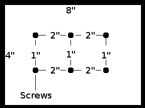 Step three: Cut four 8" pieces of the solid core wire and strip it bare. 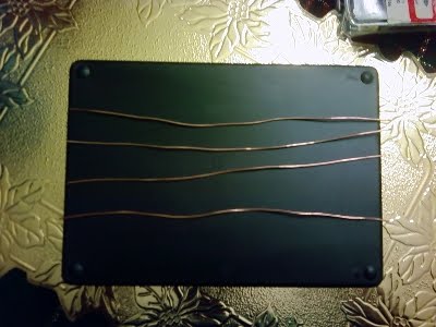 Step four: Use a marker and mark every 1" on the wire. (This is where we are going to make the bends) Step five: You will repeat this step for each wire. Each bend on the wire will be 60 degrees exactly as we will be making equilateral triangles with this fractal. I used two pairs of pliers and a protractor. Each bend will be made at the 1” marks. Make sure you visualize the direction of each bend first before making it! Use the diagram below to help. 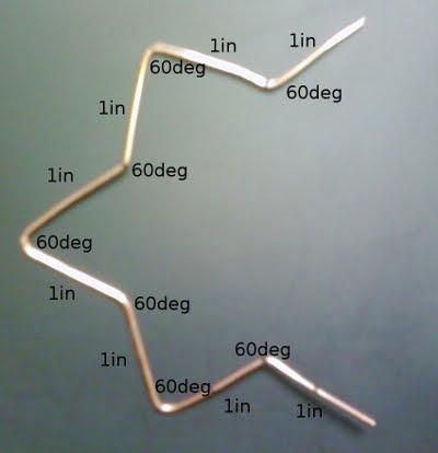 Step six: Cut 2 more pieces of wire at least 6 inches long and strip them. Bend these wires around the top and bottom screws going longways and contact the center screws. So all three are contacted. Use the wire cutter and trim unneeded wire. 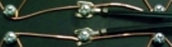 Step seven: Place and screw down each of your fractals to the corner screws. Step eight: Attach the impedance matching transformer across the two center screws and tighten them down. 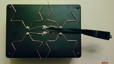 COMPLETE! NOTE: The bottom of the antenna is to the right of this picture where the transformer sticks out. You may now test your build!. Hook it up and try it out! It worked great for me! As you can see from the picture below, each time you divide each section and create a new triangle the length of the wire is the same but can fit in a smaller space by taking up room in another direction. 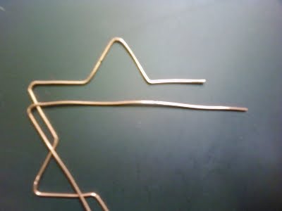 Note: I am not an expert on the subject and I don't assume to have all the answers or information 100% correct. So please, if you find any mistakes feel free to contact me and let me know and I will correct it. |